Robot Arm
|
Created and Presented By: Jacob Hoffner
Completion Date: Saturday, January 2nd For my marking period physics project, I have decided to reconstruct the Science Olympiad event, "Robot Arm". This project was quite the challenge, as it has put me through much trial and error... and believe me, many problems were faced!
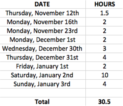
Here are some statistics on the Robot Arm: Approximated Total Number of Hours: 30.5 Hours Dimensions: 30 cm x 30 cm x 65 cm Approximated Weight: 8.8 Pounds Extends Approximately: 80 Centimeters |
Time Log:
|
Construction/Documentation Parameters
There were parameters set to the construction of this robot; here are some:
The Arm(s) may be attached to a base.
The Arm(s) must fit within a 30 cm x 30 cm x 100 cm area.
Batteries used must not exceed 14.4 volts of electricity as a total accumulation.
There were parameters set to how the robot parts and functions were documented; here are some:
Note: These parameters are only specific to the Science Olympiad portion of the event.
All actuators, energy sources, and controls must be numbered for reference.
There must be a description to all of the robot's reactions to each control input, plus the proposed plan of movement.
A Written Practice Log must be recorded for 10 runs, while recording at least 3 parameters, including the time and score of the robot's performance.
The Arm(s) may be attached to a base.
The Arm(s) must fit within a 30 cm x 30 cm x 100 cm area.
Batteries used must not exceed 14.4 volts of electricity as a total accumulation.
There were parameters set to how the robot parts and functions were documented; here are some:
Note: These parameters are only specific to the Science Olympiad portion of the event.
All actuators, energy sources, and controls must be numbered for reference.
There must be a description to all of the robot's reactions to each control input, plus the proposed plan of movement.
A Written Practice Log must be recorded for 10 runs, while recording at least 3 parameters, including the time and score of the robot's performance.
Competition Area
|
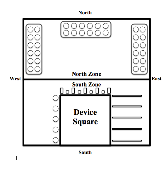
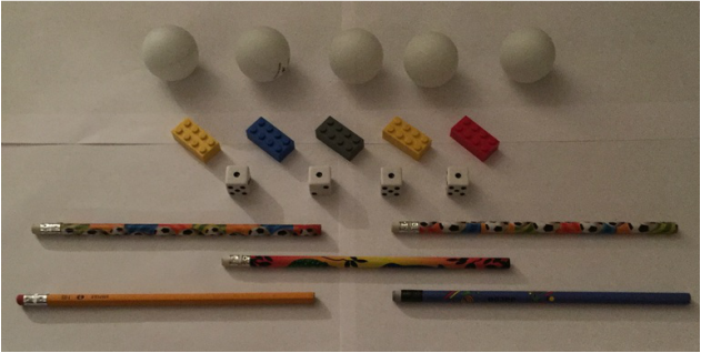
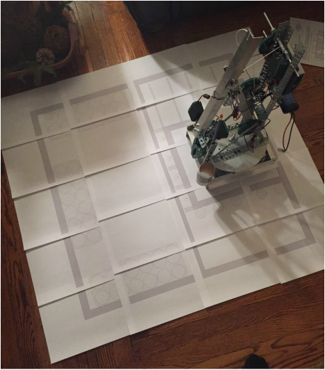
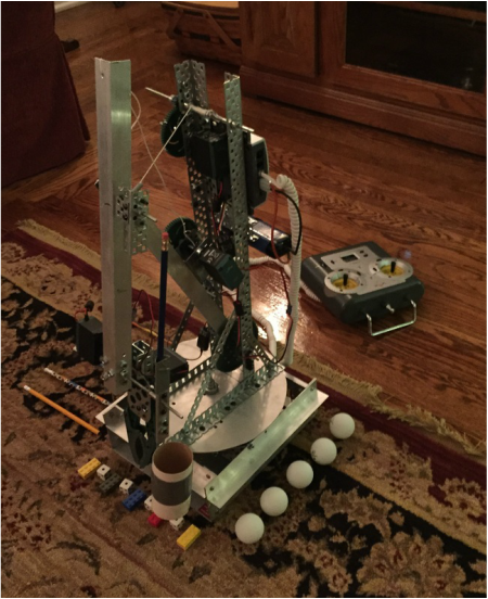
The Competition Area is a 75 cmx 75 cm square surrounded by the inside edge of tape 2.5 cm wide. The robot sits inside its 30 cm x 30 cm square. There is a North Zone and a South Zone; the robot starts in the South Zone. There are three egg cartons in the North Zone, and each egg carton has 2 x 6 egg slots. Each egg carton has two egg slots labeled with a "B". The Scoreable Items are as follows: Left: 5 Ping Pong Balls Front: Alternating 2 x 4 studded Legos (5) with 4 Dice with the "1" dot facing up. Right: 5 Unsharpened #2 Pencils |
|
Out with the Old, In with the New
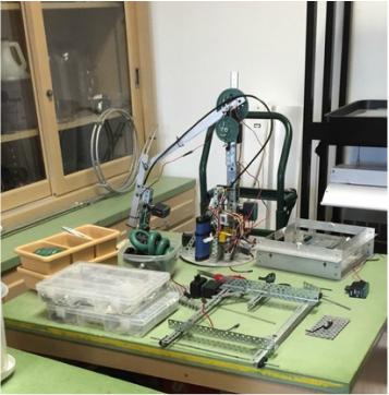
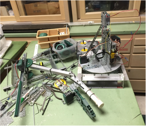
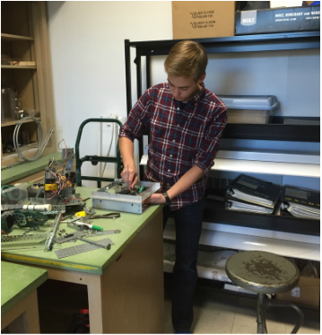
In order to begin the construction of the Robot Arm, I had to first disassemble the old Robot Arm.
|
|
|
The Start of the Arm
This Robot Arm was constructed using Vex technology and aluminum angle pieces.
The Turning Base
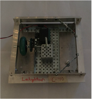
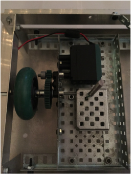
The base to the old robot arm design was saved, but modified to improve efficiency by replacing the worm gear inside with a normal gear connected to a rubberized wheel, which is used to turn the base of the robot arm. The Turning Base is controlled using a 2-wire motor.
|
|
The Tower
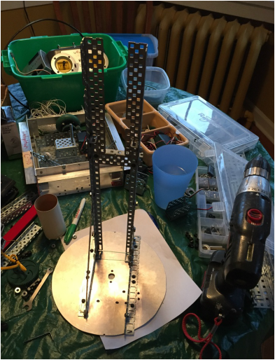
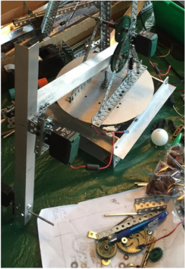
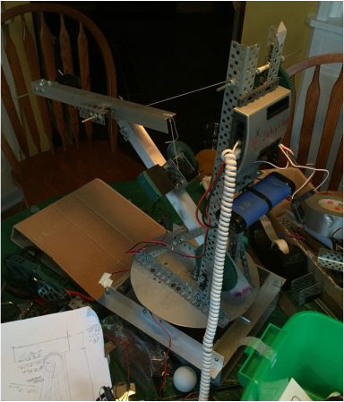
The robot is designed to use a pulley system in order to lift the arm of the robot. In order to do so, a tower had to be constructed onto the turning base of the robot to provide support to lifting the upper arm of the robot.
The Upper Arm
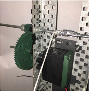
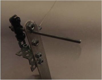
The Upper Arm of the robot arm is attached to the tower by an axle. This part of the robot was constructed out of aluminum in order to reduce the weight load the robot has to endure. The arm is then connected to the pulley system at the top of the Tower in order give leverage when lifting the Upper Arm. The pulley system is controlled by a 2-wire motor. The Upper arm contains the axle that is used to attach the Forearm to the robot; the axle is attach on each part of the arm at two different places in order to prevent instability.
|
|
|
The Forearm
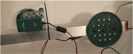
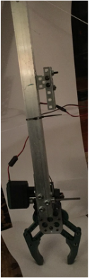
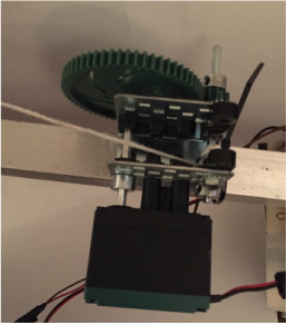
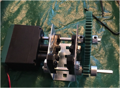
In order to yet again reduce the weight of the arm, the Forearm of the robot was constructed of aluminum. As seen in the above picture on the left, the Upper Arm is fixed with a small gear box (bottom picture on the right) on the arm. This gear box houses the pulley system for the Forearm. As does the Upper Arm, the Forearm is controlled by a pulley, which is controlled by a 2-wire motor. The Forearm is connected to the Upper Arm using an axle piece that is attached to each part of the arm at 2 different places in order to prevent instability.
|
|
|
|
The Brain
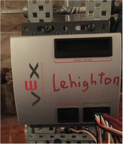
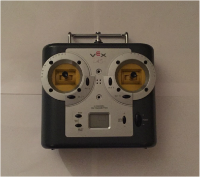
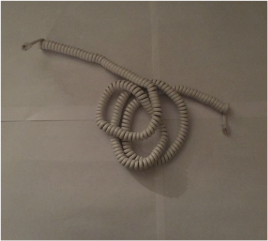
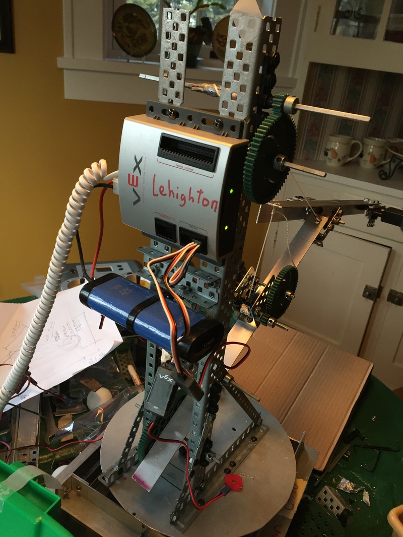
In order to start testing some of the working functions of the robot, I added "The Brain" to the robot arm. The Brain controls the entire robot by supplying the motors with power and commands. These commands come from the Vex controller I use to control the robot. The commands get to the Brain through a tether cord attached to the Vex controller and the Brain.
|
|
|
|
The Claw, Ping-Pong Ball Holder, and Pencil Poker
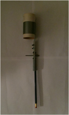
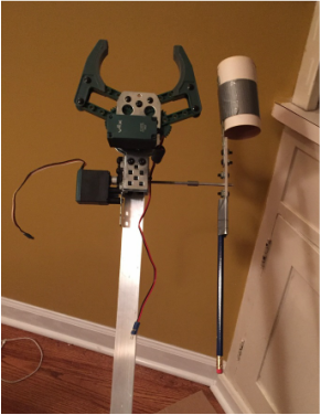
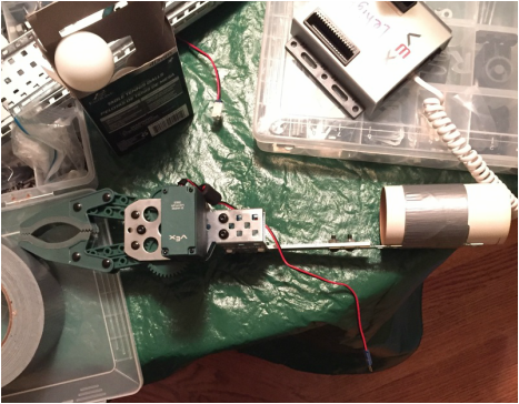
The Robot Arm is tasked with picking up ping-pong balls, Legos, and pencils, and must also roll dice. In order to do so, I attached a claw mechanism on the end of the Forearm. The claw moves using a 2-wire motor attached to it. Alongside of the claw is a hollow cardboard cylinder with two copper wires in front of one of the openings. This contraption picks up to three ping-pong balls by pushing down on them. On the other side of the ping-pong ball holder is a pencil, which is used for rolling the dice or moving objects. The robot arm can alternate between the ping-pong ball holder and the pencil by using a 2-wire motor attached to the Forearm that spins the two contraptions.
|
|
Sources of Power
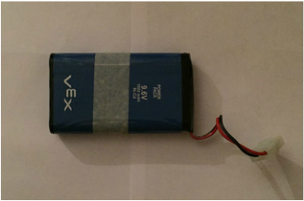
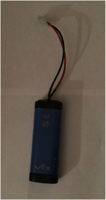
The entire Robot Arm is powered by two batteries. One 9.6-volt rechargeable battery is housed in the back of the Vex controller, while the other 7.2-volt rechargeable battery is housed on the Tower of the robot, connected into the Brain.
|
|
|
Trial and Error
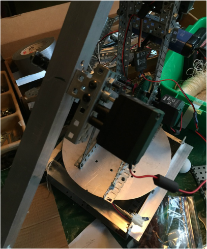
There were three main situations where mistakes made to the robot resulted in remodeling a section of it. First, the Upper arm could not take the weight of itself with the direct use of a motor on its axle using gears. So, the pulley system was used to replace this gear system, as shown above in the section, "Upper Arm". Second, the motor on the Forearm could not directly take the weight of the Forearm, so a pulley system was installed on the top of the Upper Arm to take the weight of the Forearm, as was shown above in the section, "Forearm". Third, the Arm originally had an attachment on the end of the Forearm that rotated between the Claw attachment and the Ping-Pong Ball Holder. The Claw, however, was way to heavy for the motor to bear the load, so the claw was directly attached to the Forearm, and the Ping-Pong Ball Holder and Pencil were attached to the rotating attachment instead.
Mistakes Shown Below:
|
|
The Finished Robot Arm
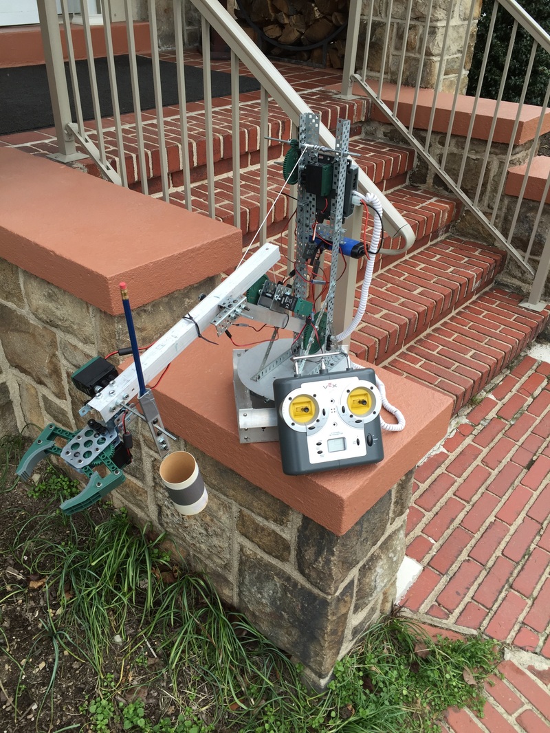
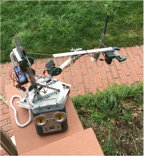
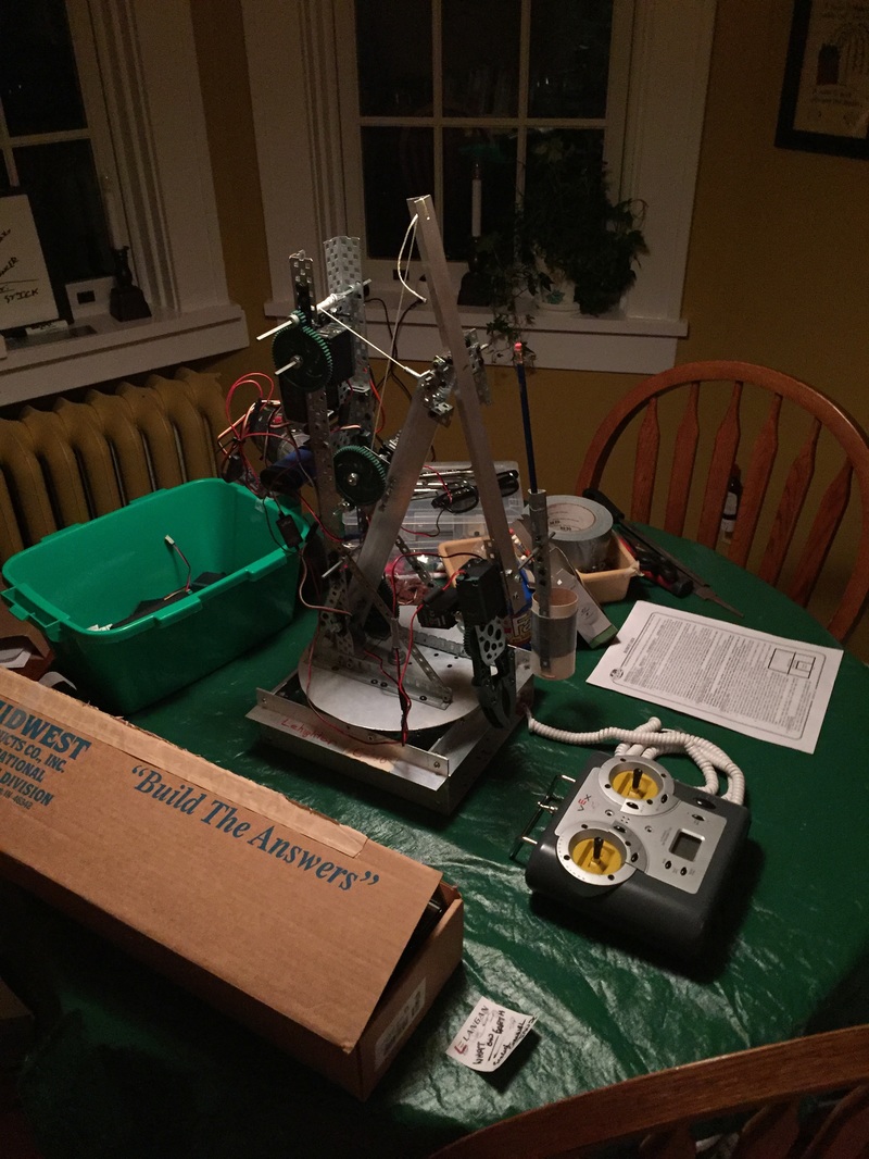
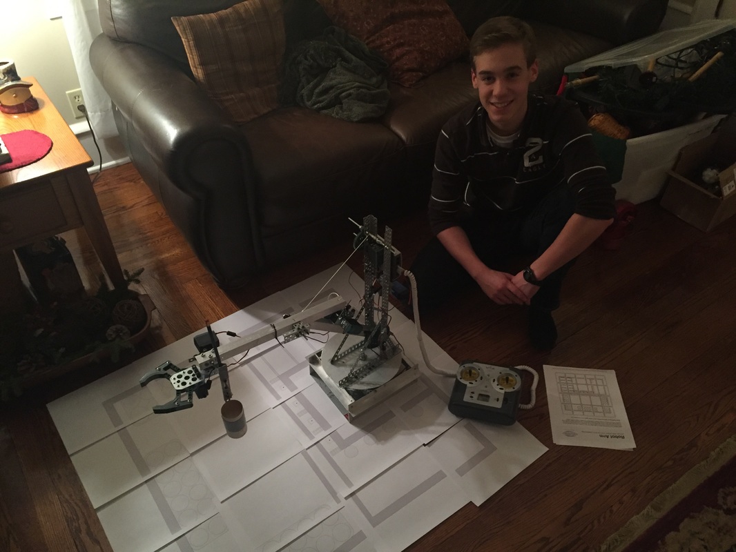
After much effort and trial and error, the Robot Arm has reached its completion. The robot arm can accommodate all of its weight through its motors, and it almost spins a full 360 degrees. It can reach almost 80 centimeters in length with its claw. It can reach a vertical height of over 75 centimeters with its claw and pencil. And it only weighs 8.8 pounds.
|
|
Below is a printable layout of the playing field of the Robot Arm, just to get a general idea of the layout.
|
|
Thank you for taking the time to appreciate this project.